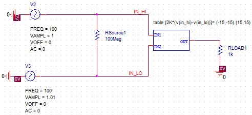

For a linear circuit with dozens of nodes, the matrix equations you formulate for Kirchoff’s laws are solvable in principle, but the problem is intractable and prone to serious errors. Real circuits being designed for complex PCBs or ICs can be very complex and often do not reduce down to a simple set of simultaneous equations that need to be solved. You can usually do this with pen and paper, as well as some simple online calculators. For simple circuits, even when nonlinear components are present, it’s quite easy to track voltage and current around a circuit. Specifically, the voltage and current need to be tracked between nodes and at nodes, respectively, using Kirchoff’s laws and Ohm’s law. The voltage and current in your circuit is distributed according to some basic physical laws. Here’s how you can use Capture CIS and PSpice to visualize power distribution before you create your PCB layout in Allegro. Your schematic design and capture tools in OrCAD/Allegro will integrate with the powerful simulation engine in PSpice, giving you a simple way to track voltage and current in your circuit as well as quickly make design changes when necessary.

Instead of using older SPICE simulators, you can visually track current in the time domain and frequency domain with the tools in PSpice. Not all SPICE simulation packages give you the tools needed to track where the voltage and current are distributed throughout a circuit, so you’re forced to read through lines of text to determine voltage and current at each node in your circuit. When your schematic editor includes a set of integrated simulation and measurement tools, it’s easy to visually track where power is distributed in your circuit. If you use the right set of schematic design tools with an integrated simulator, you won’t have to be constrained to a specific design and you can examine the electrical behavior of your system before you start your PCB layout.Īn important part of designing schematics is tracking voltage and current throughout circuits. Your schematics should also be the place where you feel free to experiment with different design choices before committing to a specific design and layout. Your schematics are where your design begins and the real engineering happens. Tracking voltage and current starts in your schematics. This set of analysis features provide a simple way to examine current and voltage distribution in a circuit before creating a PCB layout. When you need to visualize voltage and current in different circuits or sub-circuits, you should use a circuit design program with an integrated simulator. It can be difficult to track voltage and current throughout a complex system due to the large number of nodes in a circuit.


 0 kommentar(er)
